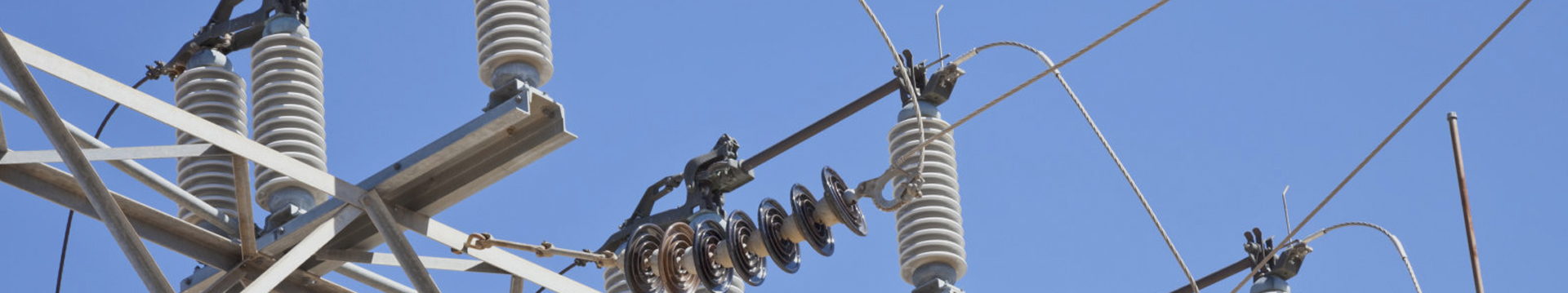
The Reliable Guardians of Power Lines: HDPE Needle Insulators
In the vast expanse of power lines, insulators are the silent guardians of power grid safety. With advancements in materials science, a new member has joined the insulator family—high-density polyethylene (HDPE) needle insulators. Their superior overall performance has secured a significant market share.
The core advantages of HDPE insulators are primarily reflected in their excellent electrical properties. High-density polyethylene itself possesses excellent insulation strength and arc resistance. Its hydrophobic surface effectively prevents dirt adhesion and continuous water film formation, significantly improving operational reliability in humid, salt spray, and industrially polluted environments. This characteristic is crucial for line safety in special environments such as coastal areas and near chemical plants.
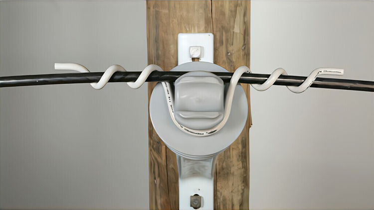
In terms of mechanical properties, HDPE material endows insulators with outstanding toughness. Unlike the brittleness of ceramics, HDPE products can deform rather than fracture under impact or extreme loads. This “flexible but not breakable” characteristic greatly reduces the risk of insulator damage caused by hail, external impacts, etc., enhancing the disaster resistance of the power lines. Meanwhile, its weight is only 1/3 to 1/2 that of porcelain insulators of the same specifications, which greatly reduces the load on towers and lowers the difficulty and cost of transportation and installation.

Furthermore, HDPE insulators exhibit strong environmental adaptability. They are resistant to acid and alkali corrosion, and withstand long-term ultraviolet radiation. Their manufacturing process is also more energy-efficient and environmentally friendly. From a life-cycle cost perspective, their long lifespan and maintenance-free or low-maintenance characteristics bring significant economic benefits to the power sector.
In conclusion, HDPE pin insulators, with their excellent electrical insulation, superior mechanical toughness, significant environmental resistance, and lightweight advantages, are playing an increasingly crucial role in power distribution lines.
| Class | 15kV | 15kV | 15kV | 25kV | 25kV | 35kV | 35kV | |
|---|---|---|---|---|---|---|---|---|
| 55-3 | 55-4A | 55-4B | 55-5A | 55-5B | 55-6A | 55-6B | ||
| Neck Designation | C | F | F | F | F | F | F / C | |
| Section Height | H (mm) | 109 | 129 | 133 | 140 | 140 | 181 | 180 |
| Diameter of Shed | D/d (mm) | 144 | 138.6 | 140 | 190 | 190 | 190 | 170 |
| Pin Thread Size | M(inch) | 1″ | 1″ | 1″ | 1″ or 1-3/8 | 1″ or 1-3/8 | 1″ or 1-3/8 | 1″ or 1-3/8 |
| Leakage Distance | (mm) | 250 | 318 | 368 | 389 | 371 | 533 | 600 |
| Dry Arc Distance | (mm) | 140 | 170 | 160 | 183 | 200 | 254 | 260 |
| Cantilever Strength | kN | 13.3 | 13.3 | 13.3 | 13.3 | 13.3 | 13.3 | 13.3 |
| Power Frequency Flashover Voltage | Dry:kV | 65 | 75 | 75 | 87 | 87 | 105 | 110 |
| Wet:kV | 42 | 45 | 45 | 52 | 52 | 70 | 75 | |
| Critical Impulse Flashover Voltage | Pos:kV | 102 | 110 | 110 | 135 | 135 | 160 | 160 |
| Neg: kV | 125 | 130 | 130 | 150 | 165 | 220 | 225 | |
| Low Fre. Puncture Voltage | kV | 160 | 170 | 170 | 180 | 200 | 230 | 230 |
| Radio Influence Voltage | Test Voltage Ground kV | 10 | 10 | 10 | 10 | 10 | 10 | 10 |
| Max. RIV at 1000kHz μV | 50 | 50 | 50 | 100 | 100 | 100 | 100 | |